

What is inside a Smart Trac
Wireless vibration sensors have fundamentally changed industrial maintenance for the better. They scale across an entire plant, run continuously, provide real-time machine health diagnostics, and eliminate the gaps that route-based inspection leaves between visits. However, a critical industry-wide challenge remains: measurement integrity. The very convenience of wireless hardware is what can often compromise data quality, leading to consistent false alarms or missed critical faults.
The root cause is frequently a mechanical design flaw known as structural instability.
Wireless sensors contain internal components - batteries, circuit boards, connectors - each with their own mass and their own mechanical behavior. When a sensor is poorly designed, those internal components do not move with the machine. They move on their own.
A heavy battery, for instance, can cause the entire unit to vibrate and respond to specific frequencies - internal component resonances and sway-induced rocking that may occur at frequencies critical for fault detection. And when that happens, the accelerometer is no longer reading the machine. It is reading the sensor's own internal dynamics.
The result is spectral distortion that looks like a fault. Alarms fire. Technicians investigate. Nothing is wrong. The cycle repeats until the team stops trusting the system - and at that point, the monitoring program has failed.
As illustrated in the mechanical model below, at specific frequencies, the internal mass of the battery begins to resonate, pulling the accelerometer with it. This motion distorts the frequency response, creating localized amplification that does not exist in the machine’s actual vibration profile. Without proper mechanical isolation, these structural artifacts compromise the precision required for reliable diagnostics.
The Smart Trac Exception: Proof, Not Promises
At Tractian, we understand that condition monitoring relies on trusted data. That is why we developed Smart Trac, our mechanical monitoring sensor, to deliver transparently validated performance. We engineered the sensor as a mechanically hierarchical system, deliberately separating the vibration sensing structure from secondary components to prevent internal structural instability.
In this architecture, high-mass components are mechanically decoupled from the sensing path. The battery is supported by a compliant polymer holder, ensuring its dominant natural frequencies are isolated from the measurement circuit. At high frequencies, the designed relative motion between these components provides beneficial passive damping to the system.
This ensures that any undesired movement of the base is effectively suppressed and does not distort the frequency response, maintaining a stable and predictable measurement stance. This mechanical behavior is depicted in the illustration below, showing the isolated resonance of the battery and the stable response maintained at higher frequencies.
Electrical connectivity is maintained via a flexible PCB - a patented Tractian solution -, providing signal transmission without the mechanical rigidity that would allow secondary structural resonances to couple into the sensing element. Most sensors solve this problem with rigid connections that inadvertently create new ones. The flexible PCB eliminates that tradeoff entirely, keeping the sensing path clean without sacrificing structural integrity. This design ensures a base-dominated response, where the sensor acts as a rigid extension of the machine rather than an independent oscillator.
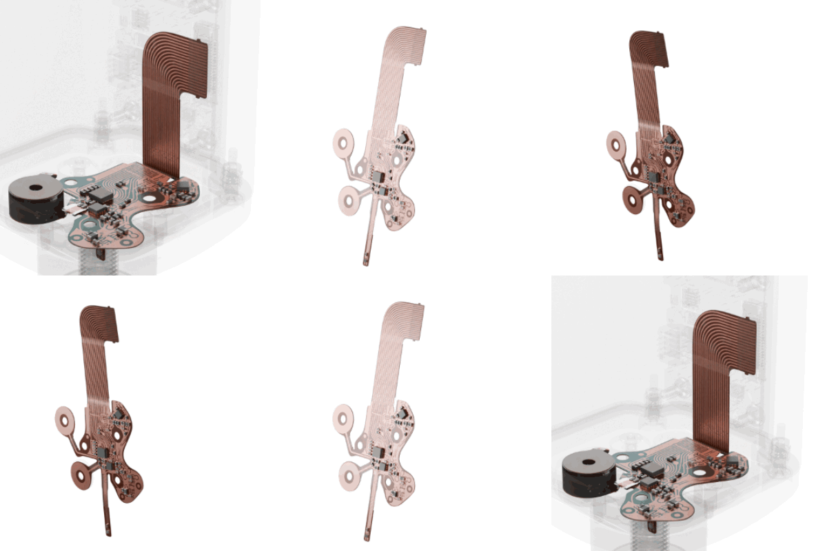
The mechanical hierarchy in simulation
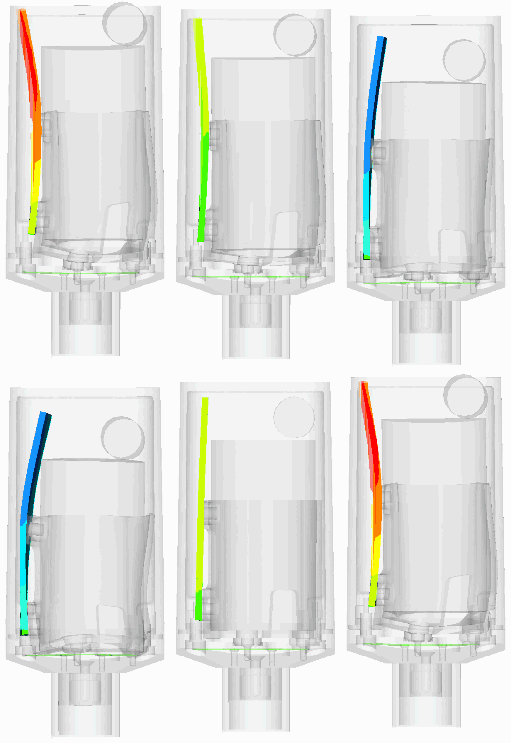 Full assembly
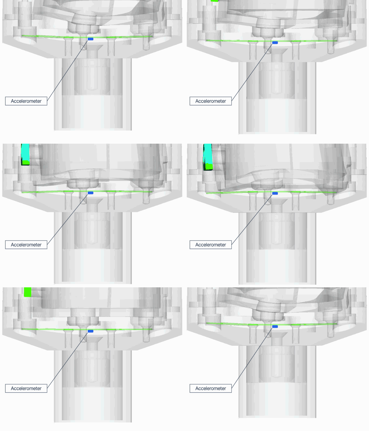 Detail · base and mounting tip
This design methodology was iteratively validated during design stages through simulations that precisely modeled the sensor's physics and dynamics, ensuring structural stability before a single physical prototype was built.
Rigorous Validation & Results You Can Trust
To verify the effectiveness of this mechanical architecture, Smart Trac was subjected to rigorous laboratory testing. Following ISO 16063-21 standards, the sensor’s frequency response was characterized using back-to-back comparison testing against a traceable reference accelerometer on a high-precision electromagnetic shaker.
The axial response characterizes the sensor's ability to accurately capture vibration along its primary measurement axis, the Z axis. The experimental results confirm the design’s integrity:
Axial frequency response (Z axis)
Smart Trac maintained a stable, flat frequency response across a 10 kHz bandwidth, with ±3 dB fidelity throughout and no pronounced resonant peaks. That high-frequency stability is what makes early-stage bearing wear, gear mesh faults, and lubrication issues detectable. These are exactly the phenomena that get buried in spectral distortion when a sensor reads its own structure instead of the machine.
While axial measurements are the primary focus of vibration analysis, a sensor's stability under lateral loads is a critical indicator of its overall mechanical integrity. Transverse (lateral) excitation testing is essential to ensure that the sensor remains a rigid extension of the machine in all directions. This stability allows the Smart Trac to capture primary fault modes regardless of the direction in which the vibration energy is centered, while simultaneously preventing off-axis energy from distorting the primary data.
Laboratory validation confirmed that the Smart Trac exhibits no high-amplification sway-induced rocking or resonant behavior that could affect measurement accuracy. This validation was conducted up to 6 kHz, a limit defined by the mechanical constraints of the calibration shaker to ensure a pure, traceable transverse signal.
The results verified exceptional isolation between axes, with minimal energy coupling into the primary measurement path. This ensures that lateral forces common in complex machinery do not contaminate axial readings, providing a clean signal for accurate machine health diagnostics.
A New Standard for Wireless Reliability
Hardware is the foundation everything else is built on. The AI models, the diagnostics, the failure predictions, the work orders - all of it starts with a sensor reading that accurately reflects what the machine is doing. Tractian's physical AI platform is only as good as the data feeding it, which is why we treat measurement integrity as an engineering priority.
The characterization of Smart Trac demonstrates that the data quality issues often associated with wireless monitoring, specifically structural instability, are not inherent flaws of the technology, but rather consequences of suboptimal mechanical design.
By prioritizing a mechanically hierarchical architecture, we have effectively eliminated the structural artifacts that lead to spectral distortion. The result is a sensor that maintains a rigid, base-dominated connection to the machine, providing a predictable and stable frequency response up to 10 kHz. This high-frequency fidelity ensures that the vibration captured is a true representation of the machine’s condition, rather than a byproduct of the sensor's own internal dynamics.
For the modern reliability program, this means more than just a wider bandwidth; it means trust in alarms and diagnostics. By validating these engineering principles through rigorous ISO-standard testing, Tractian ensures that every data is a true reflection of machine health. In an industry where precision is paramount, Smart Trac proves that you no longer have to choose between the scalability of wireless hardware and the high-fidelity accuracy of a precision instrument.